PC Remote Display
eZ2940
Johann Gysin
ZiLOG 2004 FLASH NETS CASH
Design Contest
Contents
5. PC Remote Display in action
1. Overview
1.1 Description
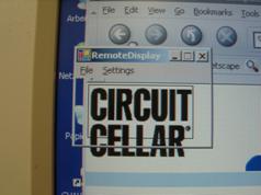
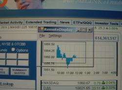
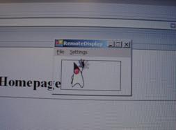
The PC Remote Display is connected serially to a PC. A small tool on the PC is periodically taking screenshots of parts of the desktop and sending these to the Remote Display which is displaying it.
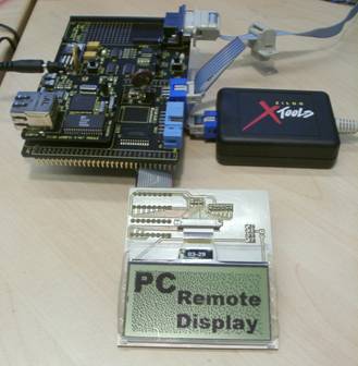
1.2 Hardware Parts
- eZ80F91 Acclaim! Contest Kit
- Graphic LCD Module; COG 128X64C1
1.3 Software Parts
- Firmware for the Microcontroller
- PC Application for taking the screenshots
2.
Hardware
2.1 LCD Connections
The Display is connected by a 8-Bit databus and 4 control lines. It is attached to the contest kit like shown on the table below.
|
LCD
Display |
Microcontroller |
Signal |
|
D0 |
PA0 |
Databit 0 |
|
D1 |
PA1 |
Databit 1 |
|
D2 |
PA2 |
Databit 2 |
|
D3 |
PA3 |
Databit 3 |
|
D4 |
PA4 |
Databit 4 |
|
D5 |
PA5 |
Databit 5 |
|
D6 |
PA6 |
Databit 6 |
|
D7 |
PA7 |
Databit 7 |
|
RS |
PC0 |
Register Select |
|
RW |
PC1 |
Read/Write |
|
E |
PC2 |
Enable (Clock) |
|
Reset |
PC3 |
Reset |
2.2 LCD Electronics
The display only needs some capacitors to generate the desired voltages to drive the LCD. All other parts are integrated in the chip on glass.
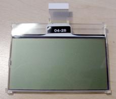
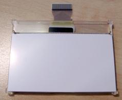
2.3 LCD Description
Type: Tecdis COG 128X64C1
Heart of the display is a Samsung ICS6B0724 driver IC.
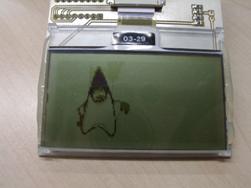
The display has a resolutiuon of 128x64 Pixels and an integrated green LED-Backlight.
It has 1kB RAM to hold the whole screen area, which can be written and read.
The memory is organized in this way:
The displayed area is divided into 8 lines or pages. Each page is divided into 128 columns of 8 Bits.
Its possible to read/write the columns in a random order.
3. Firmware
For softwaredevoloping, the delivered tool ZDS II eZ80Acclaim! was used.
I used the StarterProject in the Samples-Directory as a basis for my project.
After the building process in release mode, the image can be flashed into the eZ80.
3.1 Requirements
- Serial Interface (fast, 115200Baud)
- Timer
- LCD Driver
3.2 Interrupt setup
To use the timer and serial interface in a
nice way, its necessary to fire events if a defined time has elapsed or a
character was received.
Firstly we need the vector addresses of the desired interrupt sources from the hardware manual and define it in the code.
#define VECTOR_UART0 0x70
#define VECTOR_TIMER0 0x54
Then we need these forward declarations.
extern
void init_default_vectors(void);
extern
void set_vector(unsigned short vector,void (*hndlr)(void));
After the registers of the timer and uart are properly set up, we can assign the IRQ-Functions to the vectors.
set_vector(VECTOR_UART0,
UART_Receive);
set_vector(VECTOR_TIMER0,
TIMER0_IRQ);
Last but not least, the irqs can be activated.
UART0_IER
= UART0_IER | B0;
TMR0_IER
= TMR0_IER | B0;
3.3 Timer Interrupt
The timer is initialized to fire every 10ms.
void
timer_init(void)
{
TMR0_CTL = TMR0_CTL | B4; // Clock
Divide: 256
TMR0_CTL = TMR0_CTL | B3; // Clock Divide:
256
TMR0_CTL = TMR0_CTL | B2;
// Continous mode
TMR0_CTL =
TMR0_CTL | B1; // Force Auto Reload
TMR0_RR_L = 161; // Timerinterrupt every 10ms;
(50MHz/256)/1953
TMR0_RR_H = 7; // Timerinterrupt every 10ms;
(50MHz/256)/1953
TMR0_CTL = TMR0_CTL | B0; // Start Timer
}
Here is the timer-interrupt itself
void
interrupt TIMER0_IRQ(void)
{
char dummy;
dummy = TMR0_IIR; // Dummy read to clear
irq-flag
if (SerialTimeout < 2000)
{
SerialTimeout++;
}
// If no byte was received for 30ms,
reset bytecounter
if (SerialTimeout > 2)
{
count = 0;
}
}
Firstly the IIR-Register must be read to clear the interrupt flag.
Now it is checked if the SerialTimeout-Counter is already on the max. If not, it is incremented.
If the SerialTimeout is over 2 counts (3 counts = 30ms), we are in the timeout condition and the bytecounter for the display data is reset. This occurs if a person unplugs the serial cable while a picture is receiving.
Then the timeout resets the bytecounter count and after plugging the cable, the next picture can be received perfectly.
The SerialTimeout is reset by an uart-interrupt if a character was received.
3.4 UART Interrupt
In the UART Interrupt the data for the display is received.
void
interrupt UART_Receive(void)
{
char character;
character = UART_RBR; // Read received
character
SerialTimeout = 0; // Character was
received; reset Timeout-Counter
PictureBuffer[count] = ~character; // Put
inverted byte in Picturebuffer
// If picture is complete, set flag for
main loop to display it
count++;
if (count >= sizeof(PictureBuffer))
{
count = 0;
NewPicture = 1;
}
}
If the interrupt has fired, the received character can be copied from the RBR register into the PictureBuffer. The bytecounter-variable count is incremented by 1 so the next received character is stored in the right position in the PictureBuffer.
The SerialTimeout-variable is reset each time a character is received.
If count has the same value as the length of the PictureBuffer (8 Pages * 128 Columns = 1024), the picture is complete.
A flag (NewPicture) is set to tell the main loop that a new picture is available.
3.5 LCD Driver
The LCD Driver is located in two separate files called glcd.h and glcd.c. It has functions to startup/init the display GLCD_Init() and functions to set/reset pixels, write text, draw lines/circles/boxes
For this project, the function GLCD_WriteDisplayByte( ) is the most used.
void
GLCD_WriteDisplayByte(unsigned char page, unsigned char line, unsigned char
databyte)
{
GLCD_SetPage(PE1, page);
GLCD_SetYAddress(PE1, line);
GLCD_WriteDisplayData(PE1, databyte);
}
We set the cursor (memory pointer) to the desired page and column and then write the new databyte to this location.
The parameter PE1 is the bitposition, where the enable-signal is connected to the microcontroller. This is useful if displays with two display-controllers are connected.
In this configuration it is always PE1.
All instructions of the display are listed on page 35 of the Samsung S6B0724 datasheet.
3.6 Main program
After startup, some initializations are made to set up the timer, uart and show a startpicture on the LCD.
Now we enter the while(1) loop until powerdown
while
(1)
{
// If new picture was received
if (NewPicture)
{
index = 0; // Reset Byteindex
for (page=0; page<8; page++)
{
for (line=0; line <128; line++)
{
GLCD_WriteDisplayByte(page, line,
PictureBuffer[index]);
index++;
}
}
NewPicture = 0;
}
// If no picture was received for 10 seconds,
show standard picture
if (SerialTimeout > 1000)
{
GLCD_ShowPicture(0);
}
}
If a new picture is available (NewPicture != 0), the array PictureBuffer can be sent byte by byte to the display.
After that, the flag NewPicture is reset.
If for more than 10 seconds no data was received, a standard pictured will be showed.
4. PC Software
The PC Software is written in Microsoft Visual Studio .NET with the programming language C#.
Its required to have installed the freely
available .NET framework from Microsoft to run the .exe.
4.1 Requirements
- Serial Interface (fast, 115200Baud)
- Screenshot function
4.2 Used Components
4.2.1 Screeenshot
For taking the screenshots, I used the component ImageCapture from the codeproject website.
http://www.codeproject.com/csharp/ImageCapture.asp
4.2.2 Serial Interface
Code to communicate via RS232 was found on
the GotDotNet website.
http://www.gotdotnet.com/Community/UserSamples/Details.aspx?SampleGuid=b06e30f9-1301-4cc6-ac14-dfe325097c69
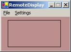
4.3 Main Window
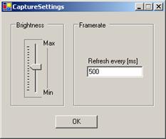
4.4 Settings Window
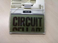
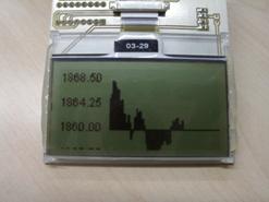
5. PC Remote Display in action
5.1
Photos
|
PC Monitor |
PC Remote Display |
|
|
|
|
|
|
|
|
|
|
|
|
|
|
|
|
|
|